Laser vibrometry is a method used for non-contact vibration measurements. As the measurement made with a laser vibrometer is non-intrusive and non-destructive it has many fields of application. Applications include automotive industry, architecture, aerospace, security and many others. One of the first inventions in laser vibrometry application in security would be the “Buran”eavesdropping system created by a Soviet inventor Leon Theremin for which he received the First Class Stalin Prize. This system used an infrared laser to covertly detect speech from a window of a room in which people were conversing. It is believed that the system was used to eavesdrop on American and French embassies as well as Stalin himself. It is considered that this system is the original predecessor of the modern laser microphones.
Nowadays there are several companies like “Polytec”or “OMS Corporation”producing
refined laser vibrometers for a range of applications. The detectable vibrational frequency range is from DC or 0 Hz up to 1.2 GHz for the most advanced systems. Depending on the application, the necessary system with the appropriate frequency range can be chosen. Low frequency measurements are widely used to test and monitor engines and motors as well as it is used in structural integrity testing whereas high frequency measurements are used in micro system analysis like micro-electro-mechanical system (MEMS) or micro-opto-electro-mechanical system (MOEMS) testing. Some companies specialize in production and distribution of laser microphones. Though it must be noted that, as this kind of device can be used to secretly eavesdrop on conversations thus breaking a person’s privacy, some of the distributors sell their systems only to law enforcement and government agencies.
The fundamental operational principle of a laser vibrometer is that the vibrational frequency of a surface can be measured by analysing the reflected laser beam from the investigated surface. Depending on the desired measurable frequency range, resolution, and sensitivity, the complexity of the system can vary from a very simple, small sized device with few components to a sophisticated system capable of distinguishing minute changes in vibrational frequency. Two main physical phenomena that give rise to the possibility of detecting vibrations at very high frequencies with great sensitivity are interference and Doppler Effect. These phenomena and their application in laser vibrometry are discussed in the following chapters.
Laser Doppler Vibrometer
Laser Doppler vibrometer (LDV) is a device that measures vibration of a surface of an object by manipulating and analysing the reflected laser beam from the object. To make the measurement possible interferometry as well, as the name of the device implies, Doppler Effect are applied. Measurement done with a LDV is non-intrusive, non-destructive, creates no mass loading on the measured object, and is relatively precise and sensitive. Because of the previously mentioned reasons it is applied in many fields like medicine, automation, architecture, production of electronics and many other.
Doppler Effect
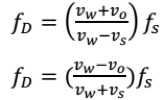
Doppler Effect is a phenomenon describing the change of frequency of an observed source of waves that is moving relative to the observer. The phenomenon applies to electromagnetic as well as mechanical waves. The frequency appears to be higher if the observer and source are moving towards each other and lower if they are moving away from each other, as shown in equation, where vwis the propagation velocity of the wave in the given medium, vois the velocity of the observer relative to the medium, vsis the velocity of the source relative to the medium, fsis the emitted frequency of the source, and fDis the observed Doppler shifted frequency. If the distance between the observer and source is decreasing then the first formula of equation is used and if the distance is increasing then the second formula of equation is used. Einstein’s Special Relativity suggests that the Lorentz Transformation must be introduced if the speed of wave approaches the speed of light, but, as the measurements are done in the same reference frame, Lorentz Transformation can be neglected

It must be noted that the velocity of the source and observer are relative to the medium where the waves propagate. Therefore for waves like sound waves, which necessitate a medium for propagation, the velocity and direction of the medium must be taken into account. This is not the case with light as it does not require a medium for propagation, consequently in calculations of Doppler shift of a light source only the velocities and directions of the source and observer must be taken into account.
Operation Principle
To detect the vibration of an object Doppler Effect is applied. If a laser beam is focused on the device under test (DUT) and DUT is moving with a certain speed, then the reflected laser beam frequency will be shifted as explained previously. By knowing the speed of vibration the vibrational frequency can be derived. Usually the output of an LDV is an analog voltage that is directly proportional to the speed and frequency of the vibration. To extract the Doppler shift frequency, which correlates with the speed of the vibration, interferometry is used. For example, Michelson Interferometer or some kind of modification of it can be used to detect the Doppler shift frequency. Looking back let us consider that mirror 2 is the DUT vibrating at certain frequency. As the DUT will be moving back and forth it will introduce a Doppler shift in the reflected laser beam, thus changing its frequency. Afterwards the reflected beam will be superimposed with the original reference beam in the beam splitter and will produce a changing interference pattern on the detector which will vary depending on the vibration of the DUT. The vibrational information afterwards can be extracted from the interference pattern either by measuring the distance between the produced interference fringes or by measuring the intensity of the light. A LDV in Fabry-Perot configuration could as well be used in the same application, as it is possible to extract the necessary information to detect the vibrational speed and frequency.
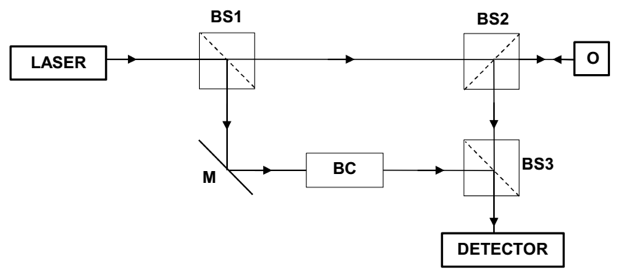
The basic operation of a practical LDV will be discussed more in detail in the following section. This is only one example of a setup as different setups are possible. The LDV optical configuration is shown in figure 4, here M stands for mirror, BS for beam splitter, BC for Bragg cell, and O is the object.

Figure 4. Simplified setup of Laser Doppler vibrometer.
Monochromatic light produced by the laser is split into two parts by the first beam splitter. The reference beam is directed towards the Bragg cell while the other part of the light after passing second beam splitter is directed on the object. The reflected beam is deflected towards the third beam splitter where it is superimposed with the reference beam and directed to the detector where an interference pattern is produced according to the objects movement. The total intensity falling on the detector can be expressed, as shown in equation, where r1denotes the optical path length of the reference beam, r2is the optical path length of the test beam, and λis the wavelength of the laser beam.

In equation the third term of the intensity sum is interference term which describes the intensity change produced by the difference in the path lengths of test beam and reference beam.
The Bragg cell shown in figure 4 is an acousto-optic modulator which shifts the laser light frequency by much lower frequency in the MHz range. If the modulating frequency of the Bragg cell is 40 MHz then a fringe pattern of 40 MHz will be produced on the detector. Without a Bragg cell it would not be possible to detect the direction of the movement of the sample as the interference pattern would be the same for both movement directions. If the information about the direction in which the object is moving is not necessary, the Bragg cell can be omitted.
Grazing Laser Vibrometer
The operational principles of a grazing laser vibrometer (GLV) will be explained. Based on this principle a vibration measurement system was developed and is thoroughly discussed in the following chapters. Even though this kind of system is less sensitive and the detectable frequency range is much lower than interferometric laser vibrometers, it is considerably cheaper and smaller and could be used in applications where the precision is not of the highest importance. For example, one application field would be continuous vibration monitoring of motors, where it is important to detect the moment when the motor is starting to fail so it could be repaired before a complete failure.
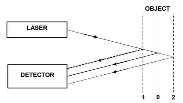
The operational basis of a GLV is much simpler than that of an interferometric vibrometer. As shown in figure 5 it consists of two main parts - the laser and the detector.

Figure 5. Schematic of a grazing laser vibrometer.
The laser beam is directed on to the vibrating object and the reflection is gathered by the detector. The underlying concept of how the vibration frequency of the object is detected is different than that which is applied in LDV. While LDV detects the frequency by detecting the velocity of movement by Doppler Effect, GLV detects the intensity changes in the reflected laser beam introduced by the vibrating object. When the object is deflected away from laser (position 2 in figure 5), the distance the laser beam must travel becomes larger. Therefore laser beam intensity that returns to detector is smaller and vice versa when the object is deflected towards the laser (position 1 in figure 5). The change in laser beam intensity is caused by the inverse square law, which states that the intensity or irradiance of a light source is inversely proportional to square of the distance it has travelled. The square law is shown in equation, where I stands for intensity of light and d stands for distance.

Another thing that must be noted is that the position of the reflection on the detector also changes with changing deflection, as shown in figure 5. For detectors that do not have a constant sensitivity over the whole area, it must be taken into account that there will be some inconsistencies because of the position change of the reflected laser beam on the detector. Immediately one major drawback of this system can be seen from the arrangement in figure 5. As the distance between the detector and object is increased it becomes more complicated to aim and direct the reflected beam onto the detector surface. But at small distances, not exceeding one meter, the alignment process is comparatively simple and fast.
The main differences between a GLV and LDV are sensitivity, detectable frequency range, resolution, and price. Advanced LDV systems that are available on the market can have amplitude resolution of 1.5 pm and maximum vibration frequency as high as 1.2 GHz. As well the price of such systems reaches as high as tens of thousands of euros. After reviewing the available devices on the market, it was visible that none of them apply the principle of previously described GLV and even the cheapest LDV systems cost in the range of thousands of euros. As will be shown in the following part of this thesis, it is possible to develop a simple low-cost vibration measurement system based on GLV operational principle.


